Details
Posted: Aug. 19, 2022

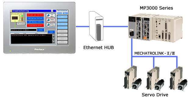
Supported Connection Devices
| Manufacturer | Product Name | Series | Note |
|---|---|---|---|
| YASKAWA Electric Corporation | Machine Controller | MP3000 series | JAPMC-CPxxxxx |
Target HMI
| Series | Resolution | Display unit type of the sample project file*1 | Screen Editor |
|---|---|---|---|
| GP4000 Series SP5000 Series | 640 x 480 dot(VGA) | GP-4501T(Analog Touch Panel) | GP-Pro EX Ver. 4.09.120 or later |
| SP5000 Series SP5000X Series | 800 x 480 dot(WVGA)*2 | Box Module:SP-5B10 Display Module:SP-5400WA | GP-Pro EX Ver. 4.09.120 or later |
| ST6000 Series | GP-Pro EX Ver. 4.09.300 or later | ||
| STM6000 Series | GP-Pro EX Ver. 4.09.350 or later | ||
|
SP5000 Series | 1280 x 800 dot (WXGA) | ST-6600WA | GP-Pro EX Ver. 4.09.300 or later |
| ST6000 Series | 1024 × 600 dot (WSVGA) | ST-6500WA | GP-Pro EX Ver. 4.09.300 or later |
*1If you use the other models, you can change a model in the GP-Pro EX project file. For details, please refer to the Technical Guide.
*2For WVGA (800×480 pixels),there is function button area at the right of the screen. Please read the manual, "Functions Added to Sample Project File for SP5000 Wide Model".
Features
- Various registers required for troubleshooting can be monitored without using a dedicated tool.
- Details of the error generated in machine controller MP3000 series can be checked.
- Abnormality content is identified based on the LED and the alarm code displayed on the CPU and troubleshooting and sections to be checked are displayed. Since the alarm code is converted into a message and the related items are displayed, the cause of the alarm can be quickly identified.
- Maintenance monitor settings of MPE720 are read, and power consumption and predicted life for each axis can be checked by using a bar graph. Power consumption can be displayed by means of a chart in any combination of axes.
- The Device Monitor (GP series standard function) and the Screen Capture function are prepared.
We do not guarantee that the operation of this sample will be uninterrupted or error-free.
Terms of use / Cautions
Please acknowledge the following terms of use before you use our download service.Download of any file signifies your agreement to the terms of use.
Terms and conditions
Download file
Update History
[Rev.05] (2022/8/19)
- Supports ST6000 Series
- Update 4.2. Target HMI Devices
[Rev.04] (2015/04/28)
- Supports MP3000 extension, Supports SP5000 Series
[Rev.03] (2014/12/25)
- Addition of character strings
- Newly created detail screens
- Placing the screen replacement switches for the detail screens
[Rev.02] (2013/6/6)
New


Summary
This sample project file is a sample program for connecting a MP3000 series of the Machine Controller, made by YASKAWA Electric Corporation, to a GP series unit.This sample project file is specialized in a primary support on site. (e.g. cause analysis of alarms, presentation of the troubleshooting, and maintenance monitoring).