- Display specifications
- Electrical Specifications
- Environmental Specification
- Structural Specification
- Interface Specification
- Input Circuit
- Digital Output Specifications
- High-Speed Counter
- Pulse Catch Input
- Pulse Output
- PWM Output
- Memory
- Panel Cut Dimensions
- External Dimensions / Parts Identification
| Display Specifications | ||
|---|---|---|
| Model No. | PFXSTC6300TADDKE | PFXSTC6300TADDCE |
| Display Type | TFT Color LCD | |
| Display Size | 5.7" | |
| Resolution | 640 x 480 pixels | |
| Effective Display Area | 115.2 x 86.4 mm (4.54 x 3.40 in) | |
| Display Colors | 262,144 colors For details about display colors, refer to the manual of your screen editing software. | |
| Backlight | White LED (White LED (Not replaceable. Please contact customer support.)) | |
| Backlight Service Life | 50,000 hours or more (continuous operation at 25 °C [77 °F] before backlight brightness decreases to 25%) | |
| Brightness Control | 16 levels (Adjusted with touch panel or software) | |
| Touch Panel Type | Resistive film (analog, single touch) | |
| Touch Panel Resolution | 1,024 x 1,024 | |
| Touch Panel lifetime | 1,000,000 times or more | |
| Electrical Specifications | |||
|---|---|---|---|
| Model No. | PFXSTC6300TADDKE | PFXSTC6300TADDCE | |
| Rated Input Voltage | 24 Vdc | ||
| Input Voltage Limits | 19.2 to 28.8 Vdc | ||
| Voltage Drop | 5 ms or less | ||
| Power Consumption | Max | 11.3 W | |
| When power is not supplied to external devices | 8 W or less | ||
| When screen turns off the backlight (Standby Mode) | 5.6 W or less | ||
| In-Rush Current | 30 A or less | ||
| Noise immunity | Noise voltage: 1,000 Vp-p, pulse duration: 1 μs, rise time: 1 ns (via noise simulator) | ||
| Voltage Endurance | 1,000 Vac, 20 mA for 1 minute (between charging and FG terminals) | ||
| Insulation Resistance | 500 Vdc, 10 MΩ or more | ||
| Environmental Specification | ||
|---|---|---|
| Model No. | PFXSTC6300TADDKE | PFXSTC6300TADDCE |
| Certification | 
 | |
| Ambient air temperature | 0 to 50 °C (32 to 122 °F) | |
| Storage Temperature | -20 to 60 °C (-4 to 140 °F) | |
| Ambient air and storage humidity | 10%...90% RH (Non condensing, wet bulb temperature 39 °C [102.2 °F] or less) | |
| Dust | 0.1 mg/m3 (10-7 oz/ft3) or less (non-conductive levels) | |
| Pollution Degree | For use in Pollution Degree 2 environment | |
| Corrosive Gases | Free of corrosive gases | |
| Air pressure (altitude range) | 800 to 1,114 hPa (2,000 m [6,561 ft.] above sea level or less) | |
| Vibration Resistance | IEC/EN 61131-2 compliant 5 to 9 Hz single amplitude 3.5 mm [0.14 in.] 9 to 150 Hz fixed acceleration: 9.8 m/s2 X, Y, Z directions for 10 cycles (approx. 100 min.) | |
| Shock Resistance | IEC/EN 61131-2 compliant 147 m/s2, X, Y, Z directions for 3 times | |
| Electrical fasttransient/burst | IEC 61000-4-4 2 kV: Power port (display unit) 1 kV: Signal ports | |
| Electrostatic Discharge Immunity | Contact Discharge Method: 6 kV Air Discharge Method: 8 kV (IEC/EN61000-4-2 Level 3) | |
| Structural Specification | ||
|---|---|---|
| Model No. | PFXSTC6300TADDKE | PFXSTC6300TADDCE |
| Grounding | Functional grounding: Grounding resistance of 100 Ω, 2 mm2 (AWG 14) or thicker wire, or your country’s applicable standard. | |
| Cooling Method | Natural air circulation | |
| Structure*1 | IP65F, UL 50/50E, Type 1, Type 4X (indoor use only), Type 13 (on the front panel when properly installed in an enclosure) | |
| External Dimensions | 169.5 x 137 x 60 mm (6.67 x 5.39 x 2.36 in) | |
| Panel Cut Dimensions | 156 x 123.5 mm (6.14 x 4.86 in) Panel thickness area:1.6...5 mm (0.06...0.2 in)*2 | |
| Weight | 0.8 kg (1.76 lb) or less | |
*1 The front face of this product, installed in a solid panel, has been tested using conditions equivalent to the standards shown in the specification. Even though this product's level of resistance is equivalent to these standards, oils that should have no effect on this product can possibly harm this product. This can occur in areas where either vaporized oils are present, or where low viscosity cutting oils are allowed to adhere to this product for long periods of time. If this product's front face protection sheet or cover glass peels off, these conditions can lead to the ingress of oil into this product and separate protection measures are suggested. Also, if non-approved oils are present, they may cause deformation or corrosion of the front panel's cover. Therefore, prior to installing this product, be sure to confirm the type of conditions that will be present in this product's operating environment. If the installation gasket is used for a long period of time, or if this product and its gasket are removed from the panel, the original level of protection cannot be kept. To maintain the original protection level, be sure to replace the installation gasket regularly.
*2 Even if the installation wall thickness is within the recommended range for the Panel Cut Dimensions, depending on the wall's material, size, and installation location of this product and other devices, the installation wall could warp. To prevent warping, the installation surface may need to be strengthened.
| Interface Specification | |||||||||||||||||||||||||||||||||||||||||||||||||||||||||||||||||||||||||||||||||||||
|---|---|---|---|---|---|---|---|---|---|---|---|---|---|---|---|---|---|---|---|---|---|---|---|---|---|---|---|---|---|---|---|---|---|---|---|---|---|---|---|---|---|---|---|---|---|---|---|---|---|---|---|---|---|---|---|---|---|---|---|---|---|---|---|---|---|---|---|---|---|---|---|---|---|---|---|---|---|---|---|---|---|---|---|---|---|
| Serial (COM1) | Asynchronous Transmission: RS-232C/422/485, Data Length: 7 or 8 bits, Stop Bit: 1 or 2 bits, Parity: None, Even or Odd, Data Transmission Speed: 2,400 to 115,200 bps, Connector: D-Sub 9 (plug) | ||||||||||||||||||||||||||||||||||||||||||||||||||||||||||||||||||||||||||||||||||||
| USB(Type A) | Conforms to USB 2.0 (Type A) x 1 Power supply voltage: 5 Vdc ±5 % Output Current: 500 mA/port Maximum transmission distance : 5 m [16.4 ft.] | ||||||||||||||||||||||||||||||||||||||||||||||||||||||||||||||||||||||||||||||||||||
| USB (micro-B) | Conforms to USB 2.0 (micro-B) x 1, Maximum transmission distance : 5 m [16.4 ft] | ||||||||||||||||||||||||||||||||||||||||||||||||||||||||||||||||||||||||||||||||||||
| Ethernet | IEEE802.3i/IEEE802.3u, 10BASE-T/100BASE-TX, Connector: Modular jack (RJ-45) x 1 | ||||||||||||||||||||||||||||||||||||||||||||||||||||||||||||||||||||||||||||||||||||
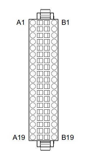
| DIO | DIO Connector: 38 pin connector (Model number: CA7-DIOCN5-01)
| ||||||||||||||||||||||||||||||||||||||||||||||||||||||||||||||||||||||||||||||||||||
| Digital Input Specifications | |||
|---|---|---|---|
| Input terminal | IN0...IN15 | ||
| Rated voltage | 24 Vdc | ||
| Maximum allowable voltage | 28.8 Vdc | ||
| Input type | Sink/Source Input | ||
| Rated current | 2.25 mA | ||
| Input resistance | 10.7 kΩ | ||
| Input points | 16 | ||
| Input points | 1 | ||
| Common design | 16-point/1 common line | ||
| Operation range | ON voltage | 15...28.8 Vdc | |
| OFF voltage | 0...5 Vdc | ||
| ON current | 2.25 mA | ||
| OFF current | 1.0 mA or less | ||
| Filtering | Normal input | 0.5 ms x N (N is 0 to 40) | |
| High-speed counter (IN0, IN2, IN4, IN6) | None, 4 μs, or 40 μs | ||
| Input signal display | No LED indicators | ||
| Status display | None | ||
| Isolation | Yes | ||
| External connection | 38 pin connector (used with Output section) | ||
| Cable length | Normal input | Maximum 50 m (164 ft) | |
| High-speed counter / Pulse catch input (IN0, IN2, IN4, IN6) | Maximum 10 m (33 ft) | ||
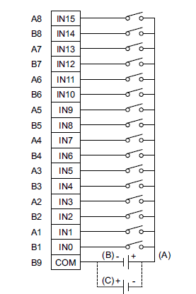
(A) 24 Vdc External power supply
(B) Source type
(C) Sink type
| Digital Output Specifications | |||
|---|---|---|---|
| Input terminal | OUT0...OUT3 | OUT4...OUT15 | |
| Rated voltage | 24 Vdc | ||
| Rated voltage range | 20.4 Vdc...28.8 Vdc | ||
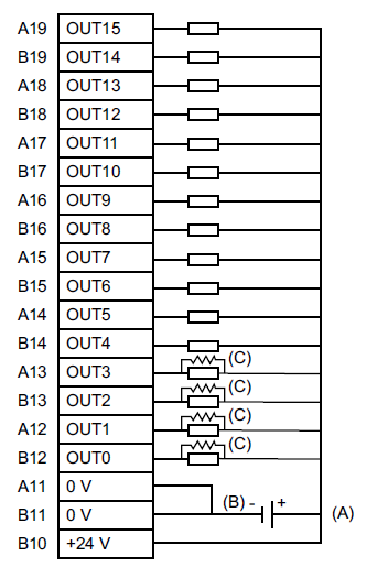
| Output type | PFXSTC6300TADDKE: Sink output | ||
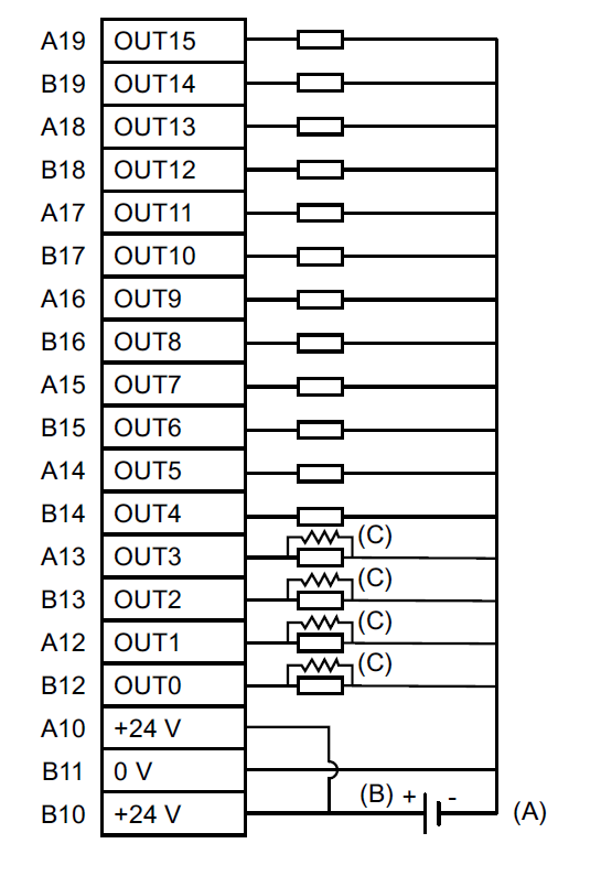
| PFXSTC6300TADDCE: Source output | |||
| Maximum load current | 0.3 A/point, total 3.2 A | ||
| Minimum load current | 1 mA | 1 mA | |
| (Pulse/PWM output unavailable) | |||
| Output voltage drop | 1.5 Vdc or less | ||
| Output delay time | OFF to ON (With output at 24 Vdc, 200 mA) | 5 μs or less | 50 μs or less |
| ON to OFF (With output at 24 Vdc, 200 mA) | 5 μs or less | 50 μs or less | |
| Type of output | Transistor output | ||
| Common lines | 2 | ||
| Common design | 8-point/1 common line x 2 | ||
| External connection | 38 pin connector (used with Input section) | ||
| Output protection type | Output is unprotected | ||
| Output points | 16 | ||
| Output signal display | No LED indicators | ||
| Status display | None | ||
| Isolation | Yes | ||
| External power supply | For Signal: 24 Vdc | ||
| Cable length | Normal input | Maximum 150 m (492 ft) | |
| Pulse/PWM output | Maximum 5 m (16 ft) | ||
*5 (Example) If the output current is 24 Vdc 50 mA, the output delay time (OFF to ON) is 1.5 μs. If more responsiveness is required or the load is light, install an external dummy resistor to increase the amount of current.
NOTE: The output terminals are not electrically protected. A short circuit or poor connection of the output wiring may cause burnout of external devices and this product. If there is a risk of the current exceeding the output rating, connect an appropriate fuse to each output terminal.
| High-Speed Counter | ||
|---|---|---|
| Input | 24 Vdc open collector | 24 Vdc open collector |
| Input points | CT0 (IN0), CT1 (IN2), CT2 (IN4), CT3 (IN6) | CT0 (IN0), CT1 (IN2) (used as pair) CT0: A Phase, CT1: B Phase CT2 (IN4), CT3 (IN6) (used as pair) CT2: A Phase, CT3: B Phase |
| Minimum pulse width (Pulse Input) | 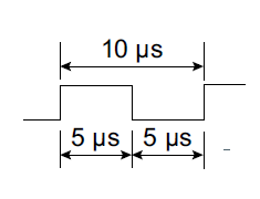 | |
| Count speed (Rise, Fall time) | 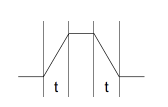
| |
| Phase | 1 phase | 90 degree phase differential |
| 2 phase signal | ||
| 1 phase+ directional signal | ||
| High speed count frequency | 100 kpps | 50 kpps |
| Count edge designation | Available | Not available |
| Count register | 32 bit UP/DOWN counter | |
| Counter mode change | Set through software | |
| Upper/Lower limit setting | Not available | |
| Preload - Prestrobe | Available | |
| Marker Input (Counter value clear) | None | IN3, IN7 |
| Pulse Catch Input | ||
|---|---|---|
| Input | 24 Vdc open collector | |
| Input points | IN0, IN2, IN4, IN6 | |
| Minimum pulse width (Pulse Input) | Input signal ON width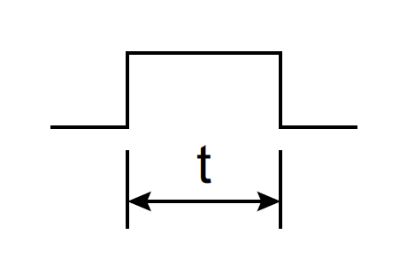 t = 5 μs or more | |
| Memory | ||||
|---|---|---|---|---|
| Model No. | PFXSTC6300TADDKE | PFXSTC6300TADDCE | ||
| Application memory | Editor : GP-Pro EX | Media | FLASH EPROM | |
| Screen area*10 | 64 MB | |||
| User font area | 8 MB | |||
| Logic program area | 132KB(Equivalent to 15,000 steps) | |||
| Free space | ー | |||
| Removable system | No | |||
| Backup memory | Editor : GP-Pro EX | Screen area | SRAM 320 KB | |
| Variable area | SRAM 64 KB | |||
| Battery | Replaceable battery / Primary battery for clock data backup | |||
*10 Use the screen area when the user font area's capacity is exceeded ー for example, when an image font or a picture font is used ー.
| Panel Cut Dimensions | ||||||
Based on the panel cut dimensions, open a mount hole on the panel.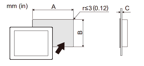 | ||||||
| External Dimensions / Parts Identification | |
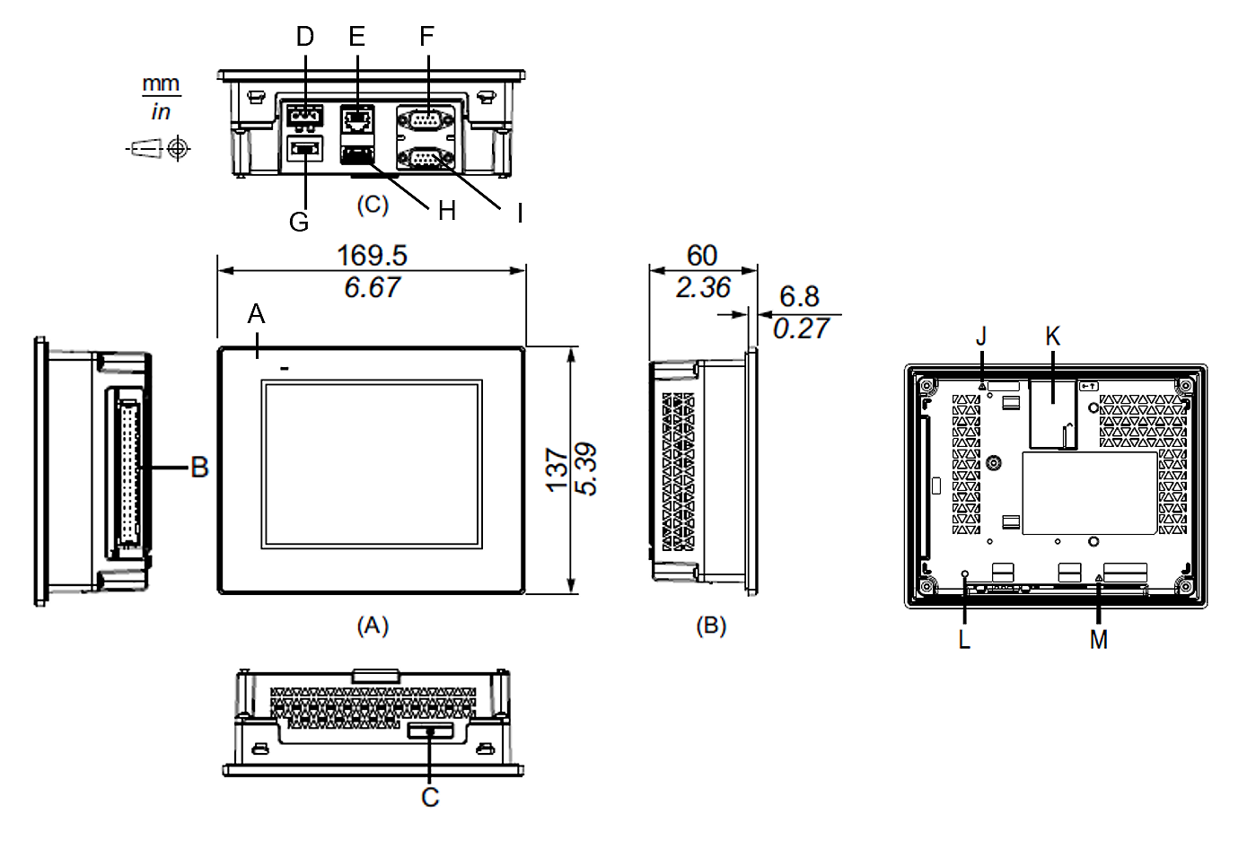 |
|

